90 Degree angle traces - Do you even RF?
Hey there folks. Today I'm going to talk about curves in PCB tracks. I've
seen a few topics here and there trying to demystify the way that tracks
should curve in order to avoid all sorts of magic stuff. There seems to be a
large consensus about avoiding 90º degrees bend at all costs, then there's a
lot of people already claiming we've been doing stuff based on tradition only
and that there's no solid reason nor practical argument to not use 90º bent
tracks. So I thought I should give my two cents on this subject. If you want to indulge in such a discussion, check out this EDA stack overflow thread.


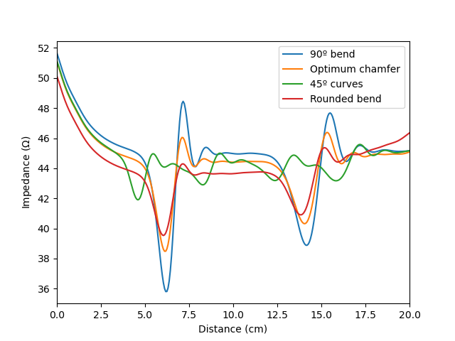
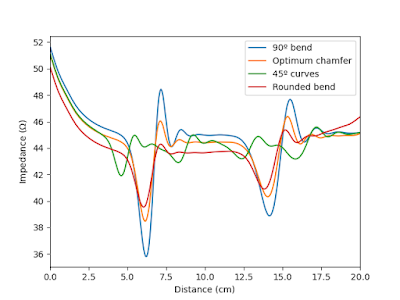 From the TDR response we can see clearly that the highest variations in impedance are from the 90 degree bend line, although the most smooth response seems to be the 45 curved line. It's also possible to see that the impedance of the line is slightly below 50 \(\Omega \), with an impedance around 46 \( \Omega\). Still, to have a better feeling for the impedance variations, I'd have to simulate the circuit up to a higher frequency. Since at 20 GHz, the resolution we can get is (very) roughly 2 mm, that means 50 points of impedance along the designed line. That's why maybe in this particular case the 45 degree curves look the best while the S-parameters tell otherwise. But I honestly didn't bother because it would not add much else to the discussion.


Well that's it for today. Next post I'll try to get back to antenna topics, but I hope to release one about 'via' transitions on RF tracks soon.
The most voted answer of said thread is certainly very detailed and mostly
demystifies religious beliefs about the 90 degree angles in the tracks.
But I also feel it ends up going overboard with statements such as:
"In fact, this is true even at very high frequencies, which I will address further down in this post. If I am wrong, by all means, show me measurements demonstrating that 90 degree corners are worse. Or better yet, if there is a measurable difference, surely it would be straight forward to build a meter that could determine if a trace had a right angle or 45 degree angle corner in it entirely by performing measurements on the input and output. Or picking up the EMI. I will eat my words if anyone can build a meter to do that."
That's where it messed up. You don't just go out and start talking
about high frequency if you know jack about that business. Unless you
consider 10 MHz to be high frequency...

I'll not indulge in philosophical discussions, nor unearth ancient
documents with references to processes that are no longer in use since
your grandma wear bikinis (you can check that thread I mentioned before
for that). I'm gonna be more pragmatic... I'll use a damn expensive EM
simulation tool and compare some PCB tracks!
I'll start simple. I picked a 100 mm long microstrip line, with 50 \(
\Omega\) characteristic impedance, calculated for a FR-4 substrate with
60 mil (1.6 mm) thickness, and designed a 180º path using four different
curve types. Let's see how it bends!

Ok so here are the example lines I'll be comparing. They are, in order,
a 90 degree bended line (I), an optimum chamfered 90 degree line (II), a
45 degree curved line (III) and a rounded corner line (IV). They all
have exactly 100 mm of length and simulated from 0.1 to 20
GHz.
 |
 |
| 90 degree bend (I) | Mitered 90 degree bend (II) |
 |
 |
| 45 degree curves (III) | Rounded corners (IV) |
And, below there's the S-parameter results for each of these lines.
Remember, S(1,1) and S(2,2) we want below -10 dB, while S(2,1) and
S(1,2) (which in this case are perfectly reciprocal) we want as close to
0 dB as possible. In the pictures below, the red line is the S(1,1) and the green line is the S(2,1).

|

|
| 90 degree bend (I) | Mitered 90 degree bend (II) |

|

|
| 45 degree curves (III) | Rounded corners (IV) |
Looking solely at the impedance perspective, if you're working below 5 GHz,
by all means, do 90 degree bends (well actually, try to read further to see
the rest of the analysis)! But, if you're working, say, at 5.8 GHz for
802.11ac or something similar, then you may want to chop the edges on those
90 degree corners, see example (II). But beyond that point, you most
certainly should look for 45 degree curves or rounded corners, both have
very similar performances up to 10 GHz, but, if you want to move to higher
frequencies, then make round corners, so that the line width is maintained
at all times.
Nevertheless, if you want to work beyond 5 GHz, then you should surely use
other material for your PCB because FR-4 ain't gonna do, as you can see from
the Insertion Loss (S(2,1)) which is considerably high (more then 3 dB),
regardless of the trace type.
To try to understand these results, we can look at the TDR response of
these lines.
We've seen the curve responses from an impedance perspective, but what
about other possible malus effects? I decided to investigate another
aspect of these lines: Radiation! This will give an idea about possible EMI
problems.
The following plots show the electric field intensity of probes at a distance of 5 mm away (in the 'z' direction), around the corners and at the center of the line path.
 |  |
| Electric field at corner in frequency domain | Electric field at corner in time domain |
 |  |
| Electric field at middle in frequency domain | Electric field at middle in time domain |
Looking at these results, although there are some particularities, I think it's safe to say that the electric field intensity for all examples is pretty close. This means that each of these examples generates a similar amount of radiation, and that means that they have more or less the same susceptibility to EMI problems.
Now, looking more closely, there's slight differences. The maximum electric field intensity generated is slightly higher for the 90º corner case, and smaller for the 45º bends (this is seen in the time domain), but the average value of the electric field intensity is more prominent in the 45º bends (this is seen in the time and frequency domain results). So, which one is actually more susceptible for EMI problems now?... The 90º bend! But by a very small margin compared to the others!

So all this stuff just to say that, unless you're working on RF applications beyond 5 GHz of frequency, you should not worry jack about the 90º bends and by all means use them. Just bear in mind the space savings that those 45º curves provide... and how satisfying it is to look at those lines all lined up making curves together...

Stay tuned!


It does brings to an end all the fight and hot discussions based on thumbs, magic and a little bit of fear on the peer reproval after an ugly and shameful 90º bend. Nonetheles, I'll still continue doing my 45° corners... You know, I ain't no hipster.
ReplyDelete